Dc Generator Schematic Diagram - Circuit Diagram Occ And Load Characteristics Of - It mainly consists of three main parts, i.e.
byAdmin-
0
Dc Generator Schematic Diagram - Circuit Diagram Occ And Load Characteristics Of - It mainly consists of three main parts, i.e.. Match each symbol with its respective component. The field windings within a dc shunt generator are connected in parallel through the armature conductors. The generated voltage is described by eq. The schematic diagram on the right is for.this is an archive based on a page that used to be at heath.htm. In actual practice, a large number of turns of the insulated copper wire are wound on a soft iron core.
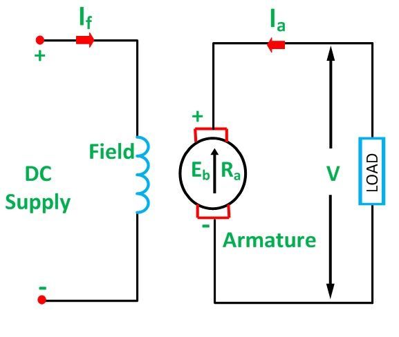
The induced emf is given from the circuit diagram as e = v + ia r a = v + (il +ish )ra load test. Three types of schematics are the single line diagram, ac schematic diagram and dc schematic diagram. The schematic diagram of the circuit arrangement needs to be included and explained. The other parts of a dc generator are magnetic frame and yoke, pole core and pole shoes, field or exciting coils, armature core and windings, brushes, end housings, bearings and shafts. Commutation (ideal commutation) practical commutation.
Direct Current Supply Distribution D C Generators Field Connection Earth Lamp Circuit from www.machineryspaces.com E g is the generated e.m.f in any one of the. Magnetic field system, armature and commutator and brush gear. High voltage dc transmission systems implemented around the globe with the advent of dc/dc converters, allowing the easy stepping up and down of dc voltages 6. The other parts of a dc generator are magnetic frame and yoke, pole core and pole shoes, field or exciting coils, armature core and windings, brushes, end housings, bearings and shafts. The induced emf is given from the circuit diagram as e = v + ia r a = v + (il +ish )ra load test. It is done specifically to know the internal and external characteristics. Draw a schematic diagram showing a dc generator, a switch, a fuse, an arc lamp, and a resistor. These are generators in which the field winding is excited by the output of the generator itself.
A simple explanation of how a dc generator works.
A simple dc generator consists of a coil of insulated copper wire. Z is the total number of armature conductor. The coil is placed between the two poles of a strong horseshoe magnet. Equivalent circuit of dc generator. Electric motors, generators, alternators and loudspeakers are explained using animations and schematics. There are three methods of excitation, and thus three main types of dc generators:. Magnetic field system, armature and commutator and brush gear. The generated electrical energy is in the form of an alternating current sinusoidal output waveform. The circulating current in the field windings produces a magnetic flux, and the phenomenon is known as excitation. In the next section, let us learn more about ac generators. A dc generator produces direct power, while an. Draw a schematic diagram showing a dc generator, a switch, a fuse, an arc lamp, and a resistor. Like dc power, there exist many devices such as power tools, radios and tv's that run off of ac
Basics 9 4.16 kv pump schematic : The schematic diagram of the circuit arrangement needs to be included and explained. Dc generators are classified based on how their fields are excited (i.e. A schematic diagram of a separately excited dc generator looks identical to figure 8 (a), but the armature current i a is reversed. This problem has been solved!
Types Of Dc Motor Shunt Series Compound Wound Motor Circuit Globe from circuitglobe.com The coil is placed between the two poles of a strong horseshoe magnet. A dc generator or direct current generator is one kind of electrical machine, and the main function of this machine is to convert mechanical energy into dc (direct current) electricity. A simple dc generator consists of a coil of insulated copper wire. 2, august 17, 2020 12v dc from tow vehicle.37 The induced emf is given from the circuit diagram as e = v + ia r a = v + (il +ish )ra load test. The circulating current in the field windings produces a magnetic flux, and the phenomenon is known as excitation. Schematics and operation of different types of motor. A dc generator produces direct power, while an.
Like dc power, there exist many devices such as power tools, radios and tv's that run off of ac
Ac generator, also known as alternators, is a machine that converts mechanical energy into electrical energy. Draw a schematic diagram showing a dc generator, a switch, a fuse, an arc lamp, and a resistor. It mainly consists of three main parts, i.e. Basics 9 4.16 kv pump schematic : This problem has been solved! There are three methods of excitation, and thus three main types of dc generators:. Both dc and ac generators convert mechanical power to electrical power. The coil is placed between the two poles of a strong horseshoe magnet. Z is the total number of armature conductor. On the other hand, though the ac and dc schematics still don't show P is the number of poles in a generator. Separately excited dc generators are rarely used in practice. Commutation (ideal commutation) practical commutation.
Dc generator diagram construction of dc generator | working principle of dc generator. The dc generator diagram is shown below. In actual practice, a large number of turns of the insulated copper wire are wound on a soft iron core. There are three methods of excitation, and thus three main types of dc generators:. Working principle of dc generator (plus diagrams) before we can explain the working principle of a dc generator, we need to cover the basics of generators.
Types Of Dc Generators Diagrams Included Electrical4u from www.electrical4u.com The magnetic flux in a dc machine is produced by the field coils carry current. The schematic diagram of the circuit arrangement needs to be included and explained. A dc generator or direct current generator is one kind of electrical machine, and the main function of this machine is to convert mechanical energy into dc (direct current) electricity. P is the number of poles in a generator. Draw a schematic diagram showing a dc generator, a switch, a fuse, an arc lamp, and a resistor. E g is the generated e.m.f in any one of the. Types of dc generators | electrical4u pertaining to schematic diagram of dc generator, image size 630 x 378 px, and to view image details please click the image. Schematic representation of a dc shunt generator.
It is done specifically to know the internal and external characteristics.
Three types of schematics are the single line diagram, ac schematic diagram and dc schematic diagram. A dc generator or direct current generator is one kind of electrical machine, and the main function of this machine is to convert mechanical energy into dc (direct current) electricity. This is known as the lorentz force. The generator is brought to its rated speed and rated voltage is built up and loaded gradually. Schematic representation of a dc shunt generator. A dc generator or direct current generator is one kind of electrical machine, and the main function of this machine is to convert mechanical energy into dc (direct current) electricity. Dc generator diagram construction of dc generator | working principle of dc generator. The dc generator diagram is shown below. A dc generator produces direct power, while an. The generated electrical energy is in the form of an alternating current sinusoidal output waveform. Egs = electronic governor system. Like dc power, there exist many devices such as power tools, radios and tv's that run off of ac N is the rotation of armature in r.p.m.
High voltage dc transmission systems implemented around the globe with the advent of dc/dc converters, allowing the easy stepping up and down of dc voltages 6 generator schematic. N is the rotation of armature in r.p.m.